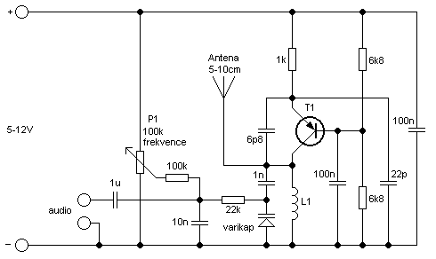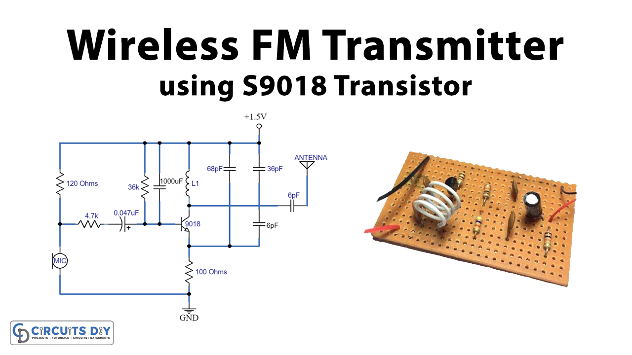
Inductor tip: If you want to make your own inductor, you can use a 24SWG wire and make an inductor out of it.

Tip 3: The inductor L1 and capacitor C4 (30pF) should be kept close. Besides, remember that there should not be any loose connections. The only thing you should be aware of is to avoid short circuit or connection of one component to another wrong component. Tip 2: It’s absolutely OK if your soldering is bad. This applies not only to this FM transmitter project, but also to any other projects. If you use too many jumpers, that may induce unwanted inductance and capacitance in the circuit and that will shift the transmission frequency of the transmitter. In this project, I have used only 1 jumper to connect -ve terminal of battery. Tip 1: You should plan your project is such a way that you use minimum number of external wires and jumpers. Please note that we don’t sell stripboard, but you can buy the FM transmitter PCB board along with the components. Strip board with vertical copper columns.R5- 33 Ohm resistor (Orange-orange-black).R4- 33 Ohm resistor(Orange-orange-black).You need to use either 1K(transmits up to 100m) or 2.2K (transmits up to 10m). 1K contributes to increment in transmission distance. R3- 2.2K resistor (Red-Red-Red)- Get 1K resistor also.

We have explained about this later on the description. It doesn’t matter if you don’t have this.
C1- 0.1uF capacitor (code- 104)- This optional. You can buy the components from, which is a store operated by our team. The radio waves from the transmitter are fed to the transmitting antenna or aerial from where these are radiated into space.Collect all the components. As the carrier frequency is very high, therefore, the audio signal can be transmitted over large distances. The process of modulation permits the transmission of the audio signal at the carrier frequency. The resultant waves are called modulated waves or radio waves and the process is called modulation. Here, the audio signal is superimposed on the carrier wave suitably. Modulator: The amplified audio signal and carrier waves are fed to the modulator. Such high power is necessary for transmitting the signal to the required distances. The power level of the carrier wave is raised to a sufficient level by radiofrequency amplifier stages Most broadcasting stations have carrier wave power of several kilowatts. Usually, a crystal oscillator is used for this purpose. Oscillator: The function of an oscillator is to produce a high-frequency signal, called a carrier wave. The amplified output from the last audio amplifier is fed to the modulator for rendering the process of modulation. This job is accomplished by cascaded audio amplifiers. The output of the microphone is fed to a multistage amplifier.Īudio Amplifier: The audio signal from the microphone is quite weak and requires amplification. When the speaker speaks or a musical instrument is played, the varying air pressure generates an audio electrical signal corresponding in frequency to the original signal. Microphone: A microphone is a device that converts sound waves into electrical waves. 
The important elements of transmitters are as follows: Transmitter: The transmitter is an extremely important device, its purpose is to produce radio frequency waves for transmission into space.


 0 kommentar(er)
